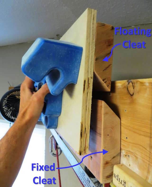
Ever since I first conceived of the Rock Prodigy Training Center, I’ve been pondering a cheap and simple mounting system that would allow for instantaneous spacing adjustments. Once the RPTC was unveiled I got a number of great ideas from other climbers. Julian Marks suggested a “French Cleat” system in this Mountain Project thread, which uses two pieces of angled lumber to create an integrated hook on the mounting structure that slides along a fixed receptacle.

This was exactly the sort of simplicity I was hoping for. Despite the assurances of several folks, I doubted that this method would provide reliable, rigid, and stable support for the RPTC. The mounting structure must be solid to ensure repeatable training loads. A board that wobbles or flexes undermines our ability to track progress and predict the proper increment of increased load between workouts. I decided to build a prototype and was impressed by the results. The finished mount was rock solid, and much easier to adjust than I had ever dreamed. Here’s a short video of the finished product in action:
Required Tools:
- Drill
- Circular Saw with a rigid blade
- Level
- Several Clamps
- Tape Measure
- Gloves, safety glasses
Optional Tools:
- Electric Sander
- Table Saw
Materials:
- 2×6, 2×8, or 2×10 lumber, 5-feet long or more
- 2×4, same length as 2×6/8/10
- 1×4, same length as 2×6/8/10
- A few short pieces of scrap 2×4
- ~Two square feet of ¾” Plywood
- 8 – 3” Wood Screws (#8 or larger)
- 6 – 2.5” Wood Screws (#8 or larger)
- 2 – 1.25” Wood Screws
I started with an 8-foot long 2×8, because I wasn’t sure how “tall’ the cleats would need to be. I went with 5.5” for the long fixed cleat and 5” for the two floating cleats (so a 2×6 would have worked for either cleat, though in retrospect, 5” for both cleats would have worked too). The first step, and by far the crux of the project, is to make an angled rip cut in the 2x piece of lumber. The cut needs to be as precise as possible, since the surface created by the cut will be the mounting surface between the two cleats. Irregularities in this surface will cause the cleats to “wobble”. For the fixed cleat you need to make a rip cut ~3.5-feet long, and for the two floating cleats you need to make a rip cut ~2.5-feet long. If you are using the same cleat height for the fixed and floating cleats, you can make one 6’-long rip cut (or if you’re using a 2×10, one 3.5′ rip cut would probably do it). Make the cut at least 6” longer than you need because you will want to trim the a few inches off each end of the finished board.

I found making the rip cut to be quite difficult, and I failed on my first attempt. A table saw or better would be really nice to have for this cut, but I was able to do it (eventually) with my circular saw. My initial error was using a “speed blade” on my circular saw, which is designed to be thin so that less material is removed while cutting, thus allowing for speedy cuts. Each time the thin blade crossed the wood grain it would flex slightly, causing the cut to veer off course. Once I switched to a thicker blade I was able to make the cut, though it was still difficult.

In preparation for the cut, I built a jig to guide the saw and make the cut as straight as possible. I fastened the 2×4 to the narrow edge of the 2×8, and then fastened the 1×4 to the inside wide edge of the 2×4 (based on the dimensions of my circular saw’s guide plate, this made the cut 5.5” from the 2x edge of the board; without the 1×4, the cut would be 5” from the 2x edge—so don’t use the 1×4 if you want your cleats to be 5” tall). I also placed some scrap 2x pieces under the entire assembly to protect my precious deck.

A few tips on the rip cut: 1) when starting, cut about 2” into the board, then back out the saw and go back in again. Repeat as necessary to ensure the saw’s guide plate is lying flat against the board and flush against the 1×4 (or 2×4) guide rail. 2) The entire time you are cutting, apply firm pressure down, and into the guide rail to prevent the saw from lifting up or veering off course. 3) Take your time! This is not an easy cut to make.

Once the rip cut was made I used an electric sander to smooth down all the new edges and the angled surface. This surface will be the mating interface between the cleats so you want it to be as smooth and uniform as possible.
Next I cut the fixed cleat down to size. This cleat is 5.5” tall, and I decided to make it 34.5” long. It could be longer, but this is all I had space for, and much longer than I need. This allows me to vary the spacing of my RPTC halves from 0” to 9.5”.

To make the two floating cleats I flipped the 2×8 around, and installed the 2×4 guide fence on the opposite edge of the 2×8, but left the 1×4 off, to create a 5” tall cleat. [Note: This isn’t ideal; I had to do this because I messed up the first rip cut and so half of my 2×8 was essentially ruined. By shortening the height of the cleat by 0.5” I was able to salvage this half of the 2×8. If I were doing it again I would make one rip cut, ~6-feet long, resulting in a cut 5.5” from the edge of the 2×6/8, and I would use that piece to make the fixed cleat and the two floating cleats.] I cut this piece into two 12.5” long pieces (about ¼” longer than one half of the RPTC). Making these longer would probably increase the stability of the finished assembly, but it would require more mounting space as well. The 12.5″ length has worked fine for me, but I notice a bit of flex when I’m using the pinch grips.

Next I cut out two 12.5” by 10” rectangles of ¾” plywood. These pieces will be attached to the floating cleats, and then the RPTC halves will be mounted to the plywood. With all the pieces cut to size, it was time to assemble the contraption.

Make two rectangles of ¾” plywood, measuring 12.5” wide by 10” tall.
The first step of assembly is to mount the fixed cleat to your mounting structure. Use a level to get this cleat lined up properly. In my case, I was mounting to a long 2×8, so I used a handful of 3” long wood screws to fasten the fixed cleat. If you are mounting to a wall with hidden studs, or some other structure, longer wood screws, lag screws, or bolts may be required. If using wood screws, use at least six, but make sure the fixed cleat is firmly attached to the mounting structure.
Next I placed the floating cleats onto the fixed cleats, and lined them up in the locations I expected to use them the most. I then attached the first plywood rectangle to the first cleat using two 2” wood screws (longer screws will penetrate the mounting surface and defeat the purpose of this entire enterprise). I lined up the rectangle so the lower horizontal edge was flush with the lower horizontal edge of the fixed cleat (this meant the top of the rectangle protrudes about 3/4” from the top of the floating cleat). Once I had the first screw in place, I used a level to get the lower edge of the rectangle level. Install the second rectangle in the same way. It helps to have a clamp for this step.

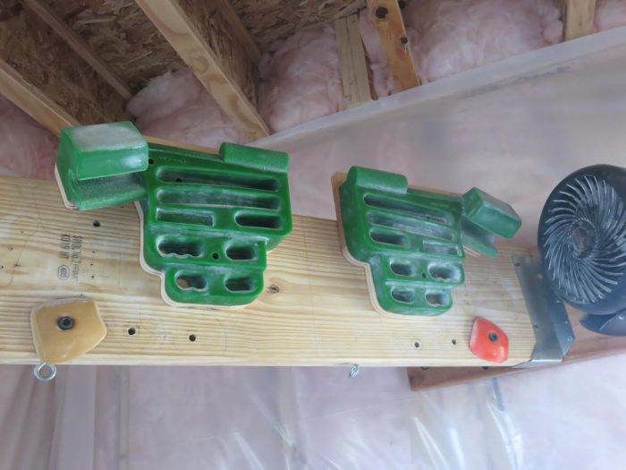
Next install each half of the RPTC onto the plywood rectangle. I installed mine flush with the lower edge of the plywood rectangle, and I used a level, placed under the edge that runs between the Thin Edge and the beveled three-finger pocket on each RPTC half, to ensure each side was installed at the correct angle (horizontal for me), and to ensure the two halves are installed at the same height. It helps to have a clamp to fine tune the alignment before installing any screws. Once aligned, use the screw lengths specified in the below pic to ensure you don’t penetrate the mounting structure or fixed cleat:

Once all the screws are installed, test your installation. You should be ready to rock! I suggest attaching or scribing a ruler onto your fixed cleat to allow for quick and repeatable adjustment of your RPTC spacing. Note the spacing used for each grip position in your Hangboard Log Sheet for future reference. I’ve been training on this mount for the past two weeks now, and I’m really happy with it. I’m looking into ways to streamline the construction of this type of mount, so if you have ny ideas, please let me know!