
In a previous article, we showed you how to build an Adjustable Mount for your Rock Prodigy Training Center so that you can take maximum advantage of the built in ergonomics of the most innovative fingerboard on the market. While it gets the job done, the French Cleat technique described in that article is difficult to execute, and the result is bulky. We’ll show you an alternate method here that can be built for about $20 in parts and an hour of work.
The finished product is shown above, and the backside view is shown below. It uses “Door Stop” hardware I found at Home Depot to drape accross a 2×10 (or 2 x whatever you like..) Besides being much lighter and lower profile than the French Cleat, this design is also extremely portable. this mounting system could be hung from any 2×8, if you were on the road and needed to get your training in…think of the possibilities…

Rear view of the finished adjustable mount.
The base board is 3/4″ plywood, which the RPTC and Door Stop hardware mount to (with T-Nuts). I had some nice scrap plywood laying around that I used, but you could use a lower grade to save some money. I used my RPTC to trace out the shape for the base boards, and cut it with a jig saw, which is ideal for cutting curves. Before you cut, plan out where the screws for the RPTC are going to be, and where the bolts for the door stops will go so that they don’t interfere. It’s a good idea to drill the holes for the Door Stop hardware before you cut, but it isn’t necessary.

I left about a 1″ margin at the top of the board, as shown in the next photo.

Note the ~1″ overlap at the top of the RPTC.
Here is how I laid out the bolt holes for the door stops:

Laying out the holes for the Door Stop. You’ll want to mount this as close to the top of the baseboard as possible.
Every climber should have a bucket of 5/16″ T-Nuts laying around, but you may need to pickup some 3/4″ x 5/16″ bolts and washers. You’ll want to torque these pretty tight so that the T-Nuts suck in to the plywood and are flush with the plywood. This will ensure the RPTC can be mounted to the base board without interference from the T-Nuts.

Torquing the bolts into the T-Nuts.
Here is the finished backplate with Door Stops, bolts, and washers:
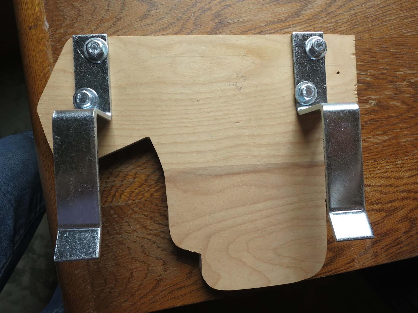
The finished backplate.
And this is the front view, showing the T-Nuts flush with the plywood for easy mounting of the RPTC:

The front side of the backplate. Note the T-nuts are flush with the plywood to allow you to mount the RPTC flush.
The next step is to mount your RPTC on the base boards. Carefully select your screws (length in particular) so that they DO NOT protrude out the back of the plywood. If they do, you’ll need to cut them off with a cutoff wheel or grinder, and that’s a pain you should try to avoid.

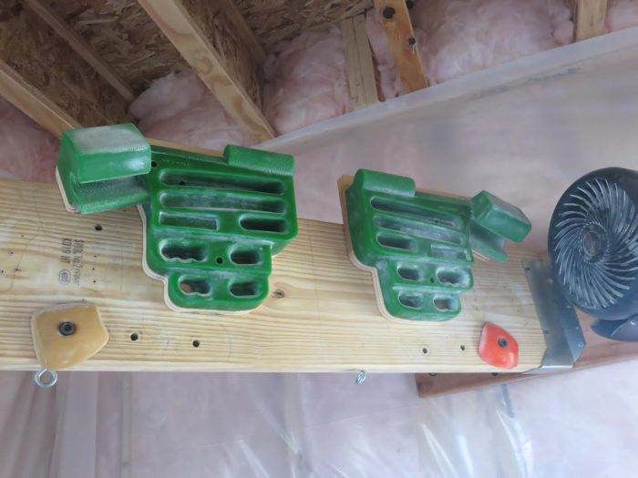
Here are the finished adjustable mounts with RPTC halves mounted:

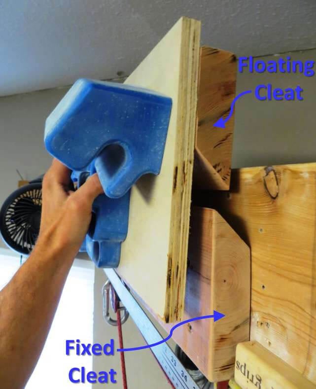
At this point, if you throw your RPTC up on a 2×10, you’ll notice some slop in the mounting. The Door Stops are not 1.5″ deep like a 2×4, they are deeper, which leaves a gap. You may be able to live with this gap (and in my experience, it isn’t a problem). If not, you’ll need to mount shims on the backside of the 2×10 to “widen” the 2×10 and eliminate that gap. Something in the range of 3/8″ to 1/2″ shim will work. I used 3/8″, and this works well for me.
Shim material mounted to the back of the 2×10 that I use for my cross beam:

Cutting out the shim material with my Jig saw:

Cutting the shims.
Finally, if you are accustomed to your hangboard residing at a particular height, you will want to relocate your cross beam. As I described in this article on how to mount a hangboard, I like the bottom of my board 81″ off the floor. The adjustable mount will raise the level of your board a few inches, so you may need to lower your crossbeam by a corresponding amount. If you have other boards or holds mounted on your crossbeam, you might want to just live with it, and build yourself a platform as described in the aforementioned article.

Lowering my cross beam to account for the increase in height provided by the door stops.
Here is the finished product, and the happy new owner of an adjustable hangboard:

![]()